Next: 2 Creating a new Up: tuto Previous: Table of contents Contents
As in tutorial 1 and 2, we assume the general goal is to design an aircraft. The specifications are given in details at the start of tutorial-1. A rudimentary geometry of the aircraft was made in tutorial-2. To start this tutorial, a more detailed CAD was produced of the aircraft. The goal of this specific tutorial is to check and assess the basics of aerodynamics on this first detailed 3D version of the design.
The design is split into 4 sets of surfaces in the CAD, each set is exported as a separated igs file, as shown below. In this case each set of surfaces forms a closed-volume, which greatly reduces chances for the software to produce bad meshes.
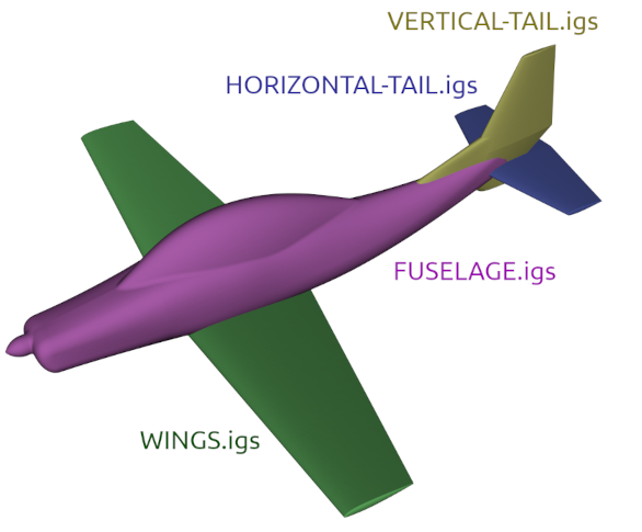
The trailing edge thickness of the wings and stabilizers are relatively large in this example: 12 mm. This is done on purpose, because the bigger they are, the faster our computations will be.
Breaking down your aircraft CAD into several .igs files allow to get more detailed results. The aerodynamic torsor of each element imported is given, which means here we will not get only the drag and lift of the entire airplane, but also the drag and lift of each of the 4 elements composing the aircraft.
Please find these igs files in the ACE of Aircraft directory, in the compressed folder named "IGSfiles.zip", or use this link : IGSfiles.zip.