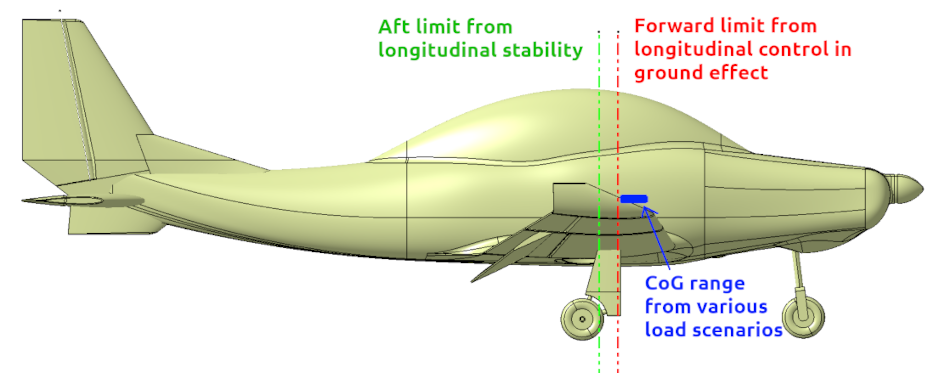
Lastly, we will estimate what is the most forward acceptable CoG according to the longitudinal force repartition. What we want is to have full control on the plane even when the CoG is very forward. That means that even if we are in ground effect, when the elevators are less efficient, we want to be able to pitch the aircraft nose upward to the stall angle, even at low speed.
To check if this is possible, we must first prepare a configuration for our geometry, corresponding to the maximum elevator deflection. in our case, this is 30°. so:
- Got to the geometry tab, select the geometry of this project.
- Click "Add a new configuration".
- Set a name, for example "Elevator-Max"
- Set the airbrake command angle to 90°.
- Set the flaps command angle to 30°.
- Set the pitch command angle to 30°.
- At the bottom, click the "Create" button.
Then you can go to the projects tab and create a new analysis in this tutorial's project. Here are the parameters that can be used:
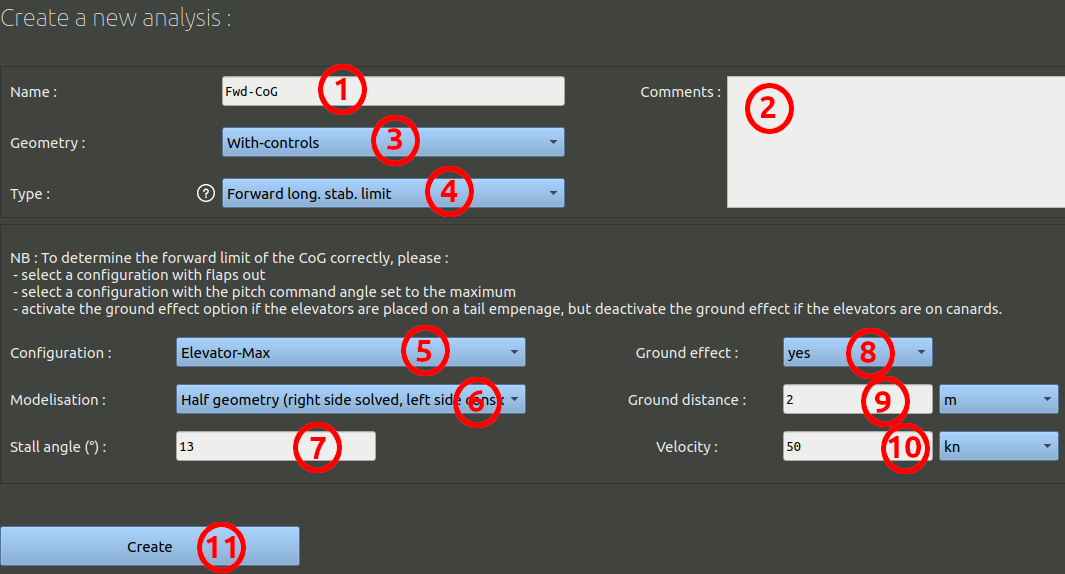
- We can name this analysis "Fwd-CoG" for example.
- It is optional, but you can add comments.
- Make sure the geometry selected is the one you created before: "With-Controls".
- The analysis type should be 'Forward long. stab. limit'.
- Make sure the configuration is the one you created before: "Elevator-Max".
- Instead of "Full geometry", choose a "Half geometry" modelisation. With this option, only the right side of the aircraft will be computed, the left side will be considered purely symmetric along the ZX plane. The computation will be faster with this option.
- Set the expected stall angle to 14°, as we observed before.
- Activate the ground effect.
- Ground distance must be set at 2 meters. This will place the aircraft tail just above the ground even at 15° of angle of attack.
- Set the velocity to the stall velocity, 50 knots.
- Validate the form at the bottom

Send the runs Created to the queue and wait for them to be processed. When the results are available, go to the "analysis results" tab and check the pitching moment plot (second graph in the page):

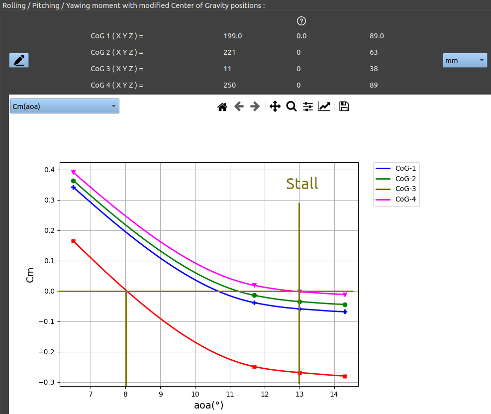
In the image shown before we have set the following centers of gravity:
- X=199 Y=0 Z=89 mm, this is the default CoG, which corresponds to the max take off weight.
- X=221 Y=0 Z=63 mm, this is the most aft mass centering estimated from our mass analysis, when there is no fuel left, but there are a passenger and luggage at the back.
- X=11 Y=0 Z=38 mm, this is the most forward mass centering estimated from our mass analysis, when there are no passenger and no luggage, but a fuel tank in front of the pilot. This is a worst scenario for take-off and currently the aircraft in ground effect cannot reach more than 8° of angle of attack in this case.
- X=290 Y=0 Z=89 mm, this is the center of gravity that will allow us to stall the aircraft even in ground effect with the current design.
The design does not guaranty the best control here, we can see that if we consider the third (Red curve) CoG, which is the most forward CoG from the mass analysis, we don't have enough force on the elevators at max deflection to stall the aircraft, we can only pitch it up to 8° angle of attack in this context. Taking off is possible, but manoeuvrability is reduced and take off is longer as the longitudinal authority is reduced.

The elevator design should be modified so that it can produce more force at maximum deflection, this would push the red line forward, and eventually in front of the blue rectangle.


