Next: 2 Creating a new Up: tuto Previous: Table of contents Contents
In this tutorial we assume the goal is to verify the aerodynamics of a NACA-23012 airfoil section with a slotted flap. The airfoil will be modeled for multiple angle of attacks and multiple flap deflections.
The airfoil primary and the flap were prepared in advance in a CAD software. It is important for ACE of Aircraft to work in the ZX Plane, with X being in the drag direction. Here is a visualisation of the CAD:
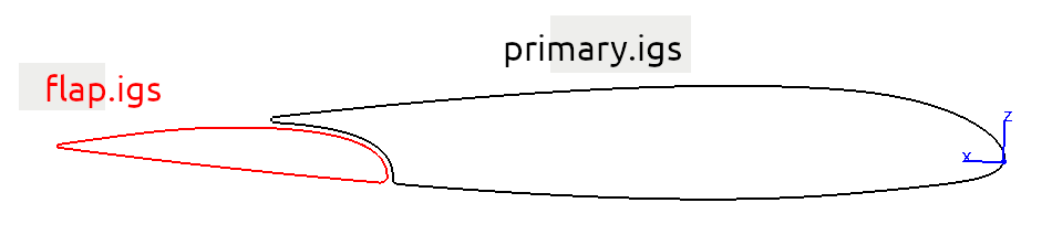
The chord length is 1 meter when the deflection is at 0°. It cannot be seen in this image, but the airfoil is extruded along Y+ and Y- so that there is at least one chord in each direction, because ACE of Aircraft receive only 3D files as input. So we actually have 3D-surface of 2 meters span.
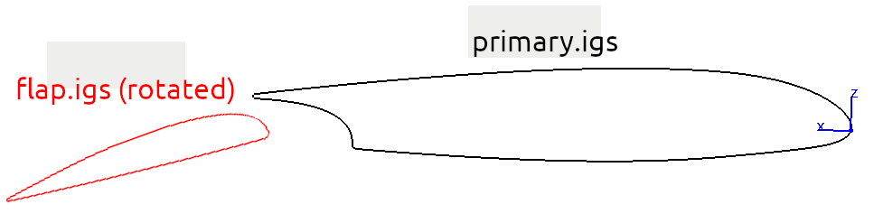
Later in the analysis, the flap will be rotated to model a deflection angle, opening a gap between primary and the flap:
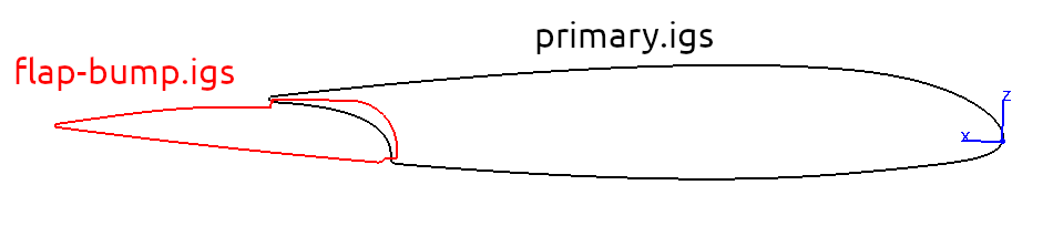
The gap is important when the flap is out. but when the flap is at zero degree of deflection, the airflow going through the gap is neglictable. A modification of the flap surface is made to help with the CFD meshing process in this case, as shown in the following picture. Tiny gaps can be difficult for the CFD process to model. Since the airflow through the gap is not important for the 0° deflection case, we offset the front part of the flap so it goes through the primary, so that the surfaces will fuse as one. This way the CFD mesher will not attempt to create air-cells between the primary and flap for this case, increasing our chances to have successful and accurate runs.
Each surface was then exported as an .igs file. Please find these files in the ACE of Aircraft directory, in the compressed folder named "IGSfiles.zip", or use this link : IGSfiles.zip.