Next: 2 Creating a new Up: tuto Previous: Table of contents Contents
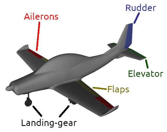
This is a continuation of the work started in the other tutorials, we are working on the same aircraft as in tutorial 1, 2 and 4. Based on the 2D geometries presented in tutorial 3, we added flaps on the design presented in tutorial 4, as well as control surfaces for pitching, yawing, and rolling and a retractable landing gear. In this tutorial we will give an example on how to define a geometry with such controls and moving parts.
The full specifications for the aircraft are presented in the introduction of tutorial 1. One point left to be assessed was the stalling speed with flaps out (Vs0) must be below 50 knots, while the maximum take-off mass is estimated at 730kg. We will check this and estimate the center of gravity range.
The image below shows the geometry with controls exported from the CAD sofware. This time we will use the STL format to exchange files from the CAD software to Ace of Aircraft. Please find these .stl files in the ACE of Aircraft directory, in the compressed folder named "STLfiles.zip", or use this link : STLfiles.zip.