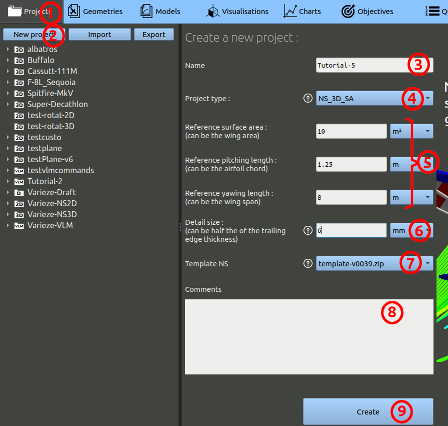
- In the navigation bar, click 'Projects'
- Then click 'New project'
- Enter the name of your choice for the project. (ex: 'Tutorial-5')
- For the project type, select 'NS_3D_SA', which is Navier-Stokes 3D Spalart-Allmaras abreviated.
- Set the parameters : Ref surface area = 10 m² ; Ref pitching length = 1.25 m ; Ref yawing length = 8 m.
- The detail size parameter should generally be less than half the thickness measured at the trailing edge of the wing and stabilizers. In our case the detail size parameters can be set at 6 mm. The other meshing parameters can be set to the default values: coarse refinement for the low-curvature surfaces and a prism expansion ratio of 1.25.
- The Template NS is a script version for processing the Navier-Stokes runs. Choose the one with the highest version number.
- You can add comments, but it is optional.
- Finally, click the 'Create' button.
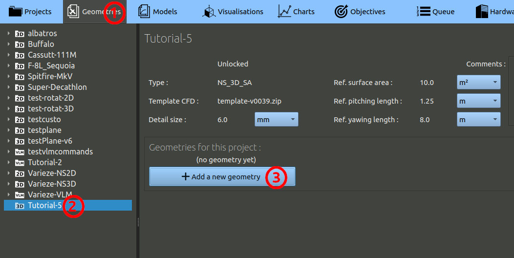
- In the navigation bar, click 'Geometries'
- In the tree on the left, choose the project you created at the preceding step.
- Finally, click the 'Add a geometry' button.
In the geometry creation form, set the parameters as:
- Name it 'With-controls' for example.
- You can add comments, but it is optional.
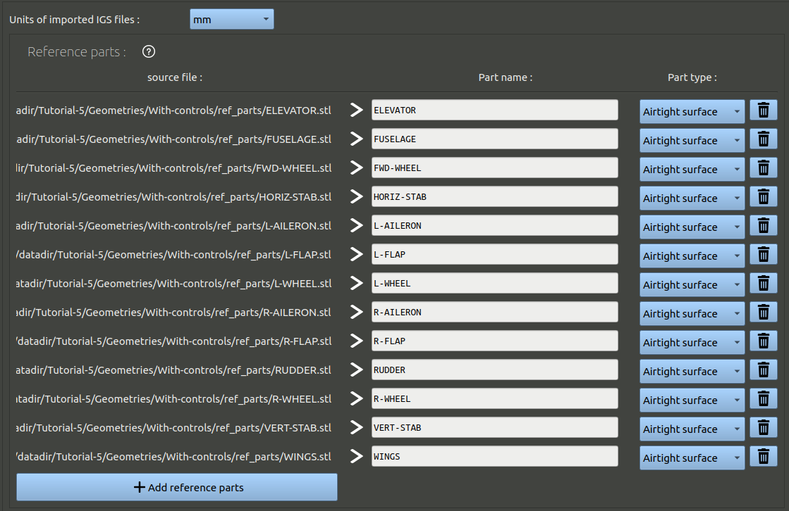
- Under the spitfire image highlighting the axis expected in the CAD, set the units of the CAD. The files provided have been exported in millimeters.
- Click the button to add reference parts, select the path to the stl files provided before, add all the stl files present in the "ref-parts" sub-directory.
You should obtain this:
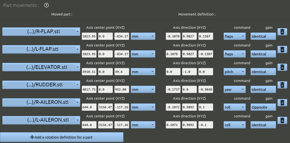
Now, let's define the part movements, starting with part rotations. Use the button "Add a rotation definition for a part" and copy the values as displayed in the following image:
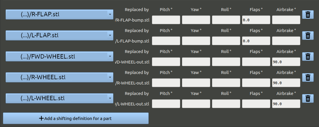
Then, use the button "Add a shifting definition for a part" and copy the values as displayed in the following image:
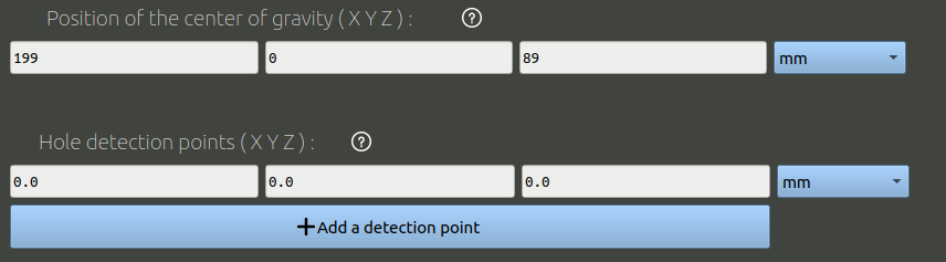
Let's end the geometry creation process:
- Set the center of gravity to 199 / 0 / 89 [mm].
- The hole detection point is used to check the integrity of surfaces given. It is a point that is inside the solid given. Here the coordinate 0 / 0 / 0 will work.
- Skip the refinement parameters and go to the bottom to create the geometry.
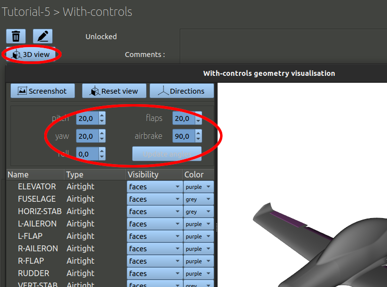
Once created, you can click the "3D view" button to visually check how the parts where imported. on the top left side you can change the command angles and check the part rotation are defined properly.
Then, you can go to the bottom of the geometry page and click the button "Add a configuration", we will need a landing flight configuration with the flaps extended and landing gear out.
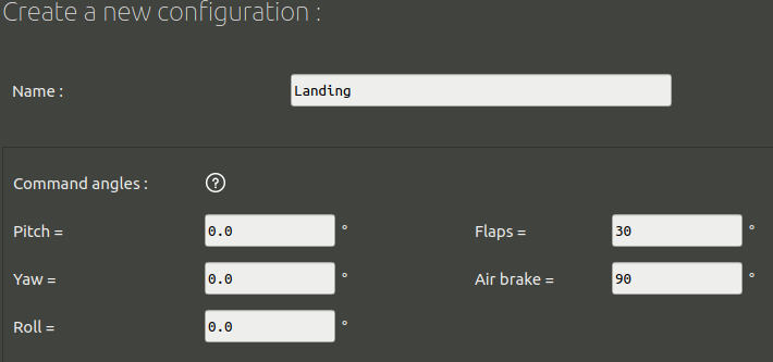
In this form:
- Set a name, for example "Landing"
- Set the airbrake command angle to 90°.
- Set the flaps command angle to 30°.
- At the bottom, click the "Create" button.