We expect the stall to happen between 12 and 15° approximately with the flaps out. But we must find the actual stall angle. In order to do that we create a first analysis:
- In the navigation bar, click 'Projects'
- In the tree on the left, choose the project corresponding to this tutorial.
- Click the 'Add a new analysis' button.
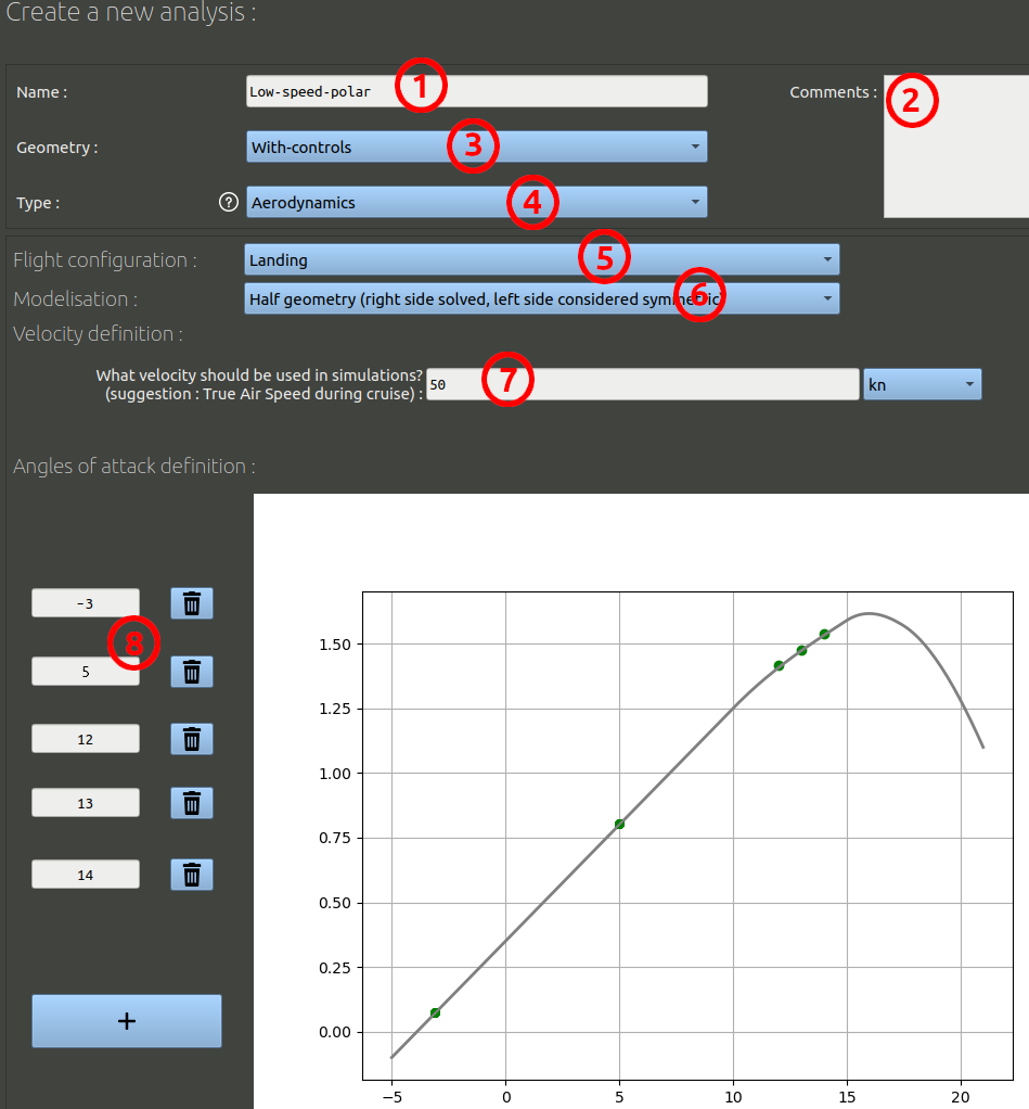
Then, in the analysis creation form we can set the following parameters:
- We can name this first analysis "Low-speed-polar" for example.
- It is optional, but you can add comments.
- Make sure the geometry selected is the one you created before: "With-Controls".
- The analysis type should be 'Aerodynamics'.
- Make sure the configuration is the one you created before: "Landing".
- Instead of "Full geometry", choose an "Half geometry" modelisation. With this option, only the right side of the aircraft will be computed, the left side will be considered purely symmetric along the ZX plane. The computation will be faster with this option.
- Set a 50 knots air speed.
- We will use the following angles of attacks: -3 / 5 / 12 / 13 / 14.
- Validate the form at the bottom
In the analysis page, make sure the tab selected is the 'Analysis set-up' tab, you should see a list of runs. Send them all to the Queue, and wait for the runs to be fully processed. This can take a day or two depending on your hardware.
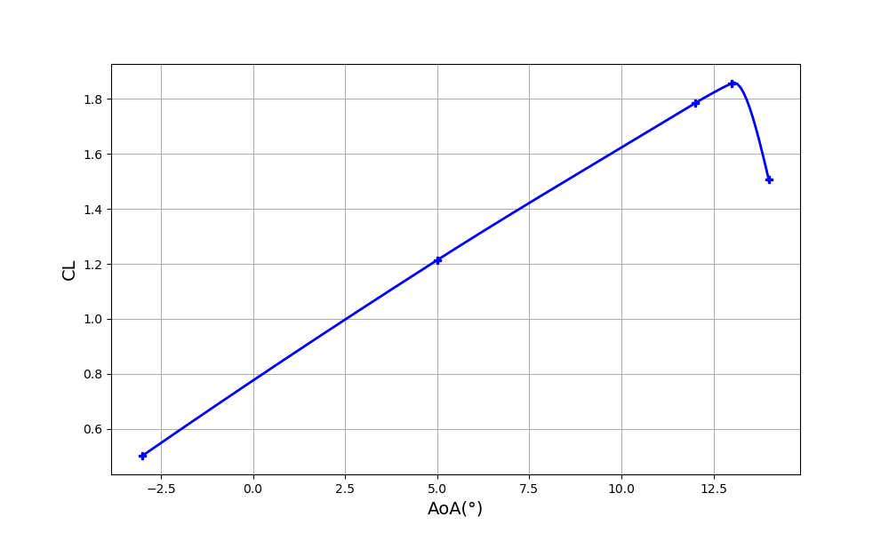
Once all the runs have been processed, Go back to the analysis page, and go to the "analysis-results tab". At the top of this tab you should find a graph with can plot the Lift, as shown in the following image. We can note from this that the maximum lift coefficient is found at 14°. This will be useful to check the stalling velocity later. If we wanted a very precise value we could try to find out the exact angle at 0.1° accuracy by adding more runs in the analysis, but for this tutorial, at this point we will assume 1° of accuracy is enough at this point.
Scroll down to the second graph displaying the pitching moment depending on the angle of attack. Use the tool to edit the center of gravity. We will test the 4 following CoG points:
- X=199 Y=0 Z=89 mm, this is the default CoG, which corresponds to the max take off weight.
- X=221 Y=0 Z=63 mm, this is the most aft mass centering estimated from our mass analysis, when there is no fuel left, but there are a passenger and luggage at the back.
- X=11 Y=0 Z=38 mm, this is the most forward mass centering estimated from our mass analysis, when there are no passenger and no luggage, but a fuel tank in front of the pilot.
- X=410 Y=0 Z=89 mm, this is what seems to be the aft limit of the CoG from the longitudinal aerodynamics, as explained later.
You should get an image comparable to the following one:
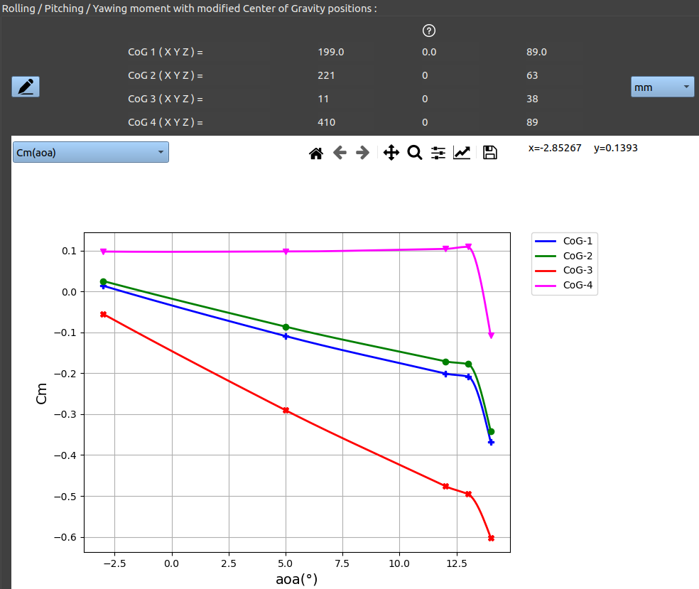
The purple curve, "CoG-4", correspond the absolute aft limit of the CoG range from a aerodynamic-longitudinal analysis. At this CoG position the curve becomes flat, which means the horizontal tail can no longer stabilize the aircraft.