Next: 2 Creating a new Up: tuto Previous: Table of contents Contents
In this tutorial we will see how to model under-cowl flow around the engine and check the cooling performance. We consider an hybrid UAV, having 4 electric VTOL propellers, and a push propeller driven by a 2 strokes DA100L engine.
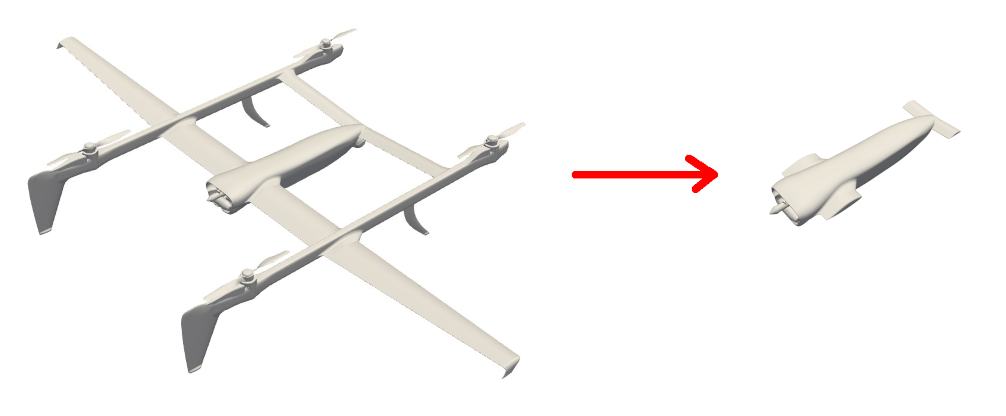
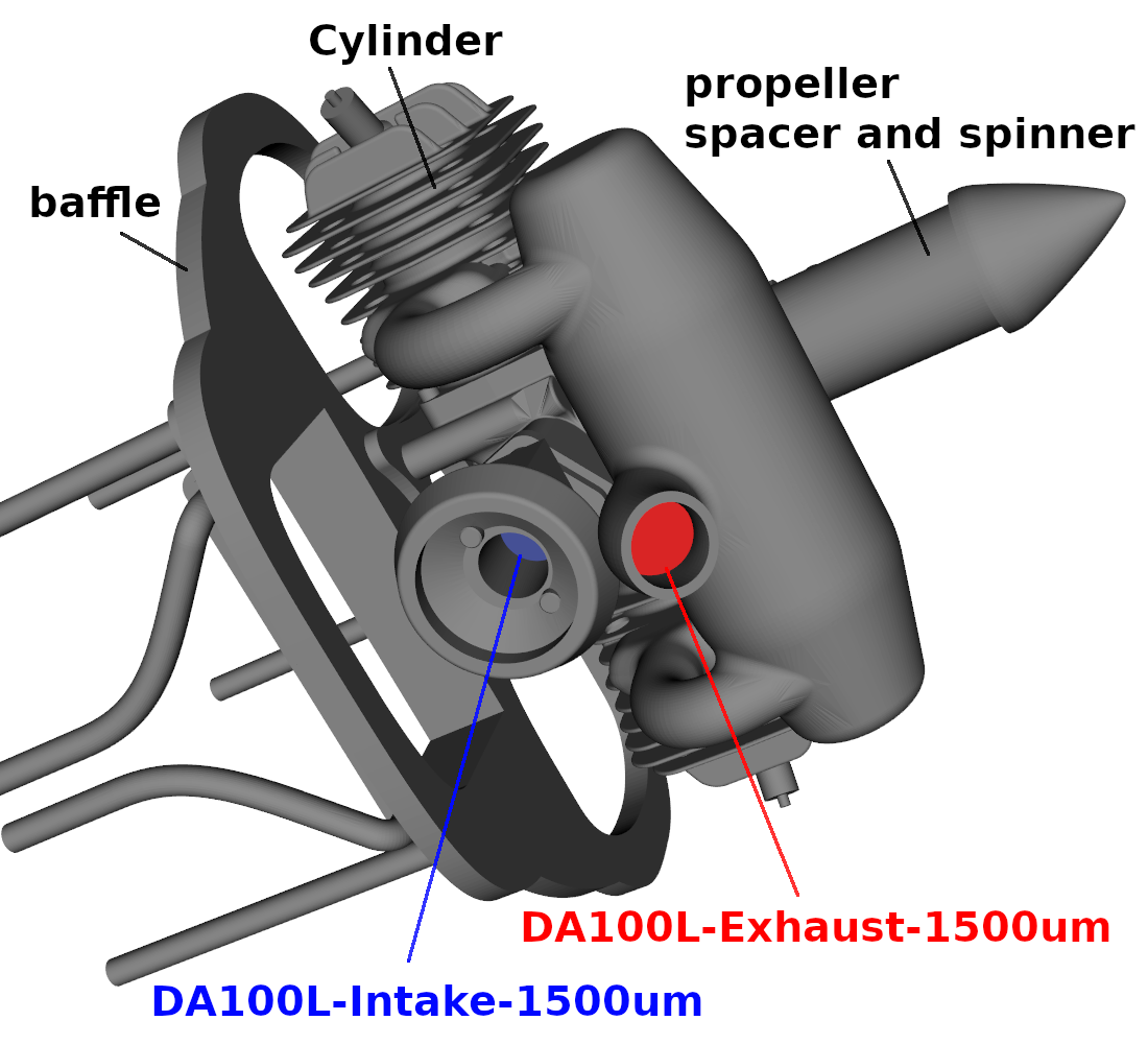
At the rear of the fuselage, there is a detailed model of the engine. under the wings, intakes let the air go inside the fuselage to the engine compartment. The air can go though large holes in a structural baffle, then go around the cylinders, then exit the rear of the fuselage before passing through the push propeller. The engine have a surface that can be used to intake air, and one for the exhaust.
Two versions of the air inlet ducts and baffle will be simulated to determine which version is better for cooling, and a more advanced post-processing will be completed. The push propeller will be modeled with a blade element model inside a cylinder, as shown by the yellow part on the following image. Two porous volumes will also be used: one to model a radiator and another one to model the air filter near the engine air admission. Three surfaces are also defined in the baffle holes, to be able to visualise the pressure and velocity gradients of the air passing through.
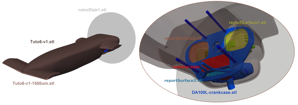
The aircraft and engine are broken down into several .stl files to get specific detailed results on each parts. The more specific details you want, the more specific parts you need. Breaking down surfaces in different parts can also allow you to put different meshing conditions on different surfaces, to refine some areas specifically. However, the more parts there is, the more RAM needed to compute forces at the end of the solving phase.
Please find these stl files in the ACE of Aircraft directory, in the compressed folder named "STLfiles.zip", or use this link : STLfiles.zip.