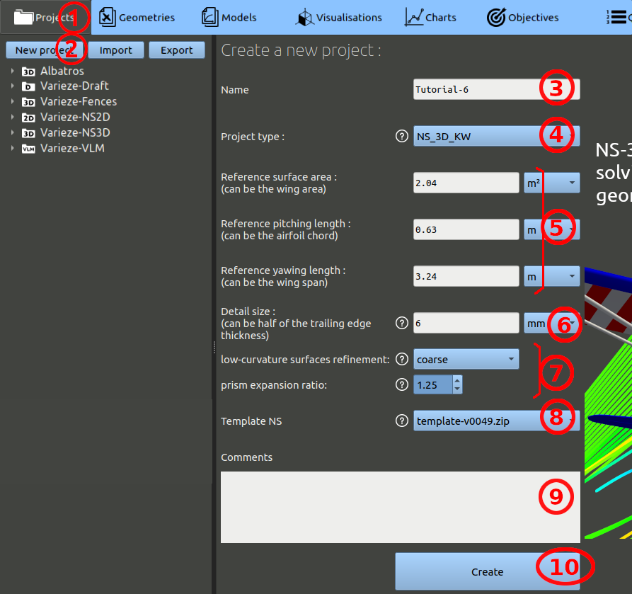
First, we have to create a project:
- In the navigation bar, click 'Projects'
- Then click 'New project'
- Enter the name of your choice for the project. (ex: 'Tutorial-6')
- For the project type, select 'NS_3D_KW', which is Navier-Stokes 3D K-Omega abreviated (a K-omega SST turbulence model will be used).
- Set the parameters : Ref surface area = 2.04 m² ; Ref pitching length = 0.63 m ; Ref yawing length = 3.24 m.
- The detail size parameter should be set at 6 mm.
- Set a "coarse" refinement on low-curvature surfaces, and a prism expansion ratio of 1.25.
- The Template NS is a script version for processing the Navier-Stokes runs. Choose the one with the highest version number.
- You can add comments, but it is optional.
- Finally, click the 'Create' button.
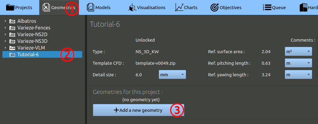
Then, we can create our first geometry:
- In the navigation bar, click 'Geometries'
- In the tree on the left, choose the project you created at the preceding step.
- Finally, click the 'Add a geometry' button.
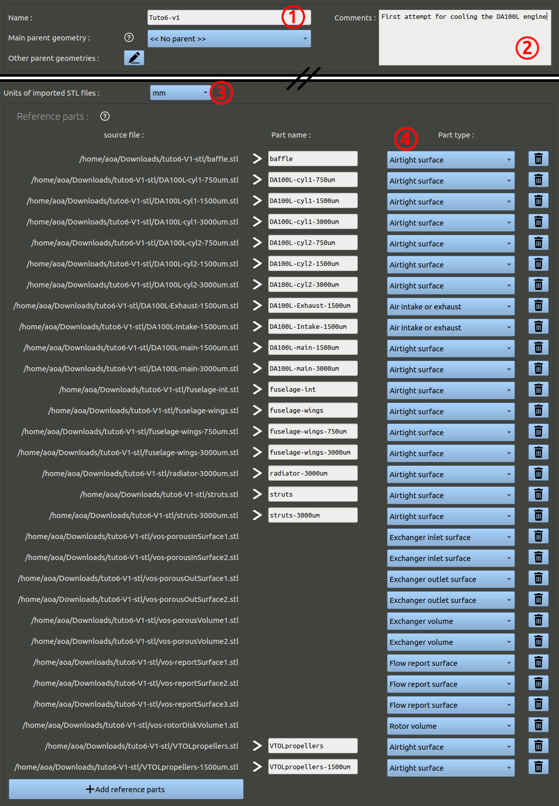
In the geometry creation form, set the parameters as:
- Name it 'Tuto6-v1' for example, as this is the first version of the geometry.
- You can add comments, but it is optional.
- Under the spitfire image highlighting the axis expected in the CAD, set the units of the CAD. The files provided have been exported in millimeters.
- Click the button to add reference parts, select the path to the stl files provided before, add all the stl files present in the "v1" sub-directory. Set the part type as below, make sure to set the intake and exhaust of the DA100L correctly.
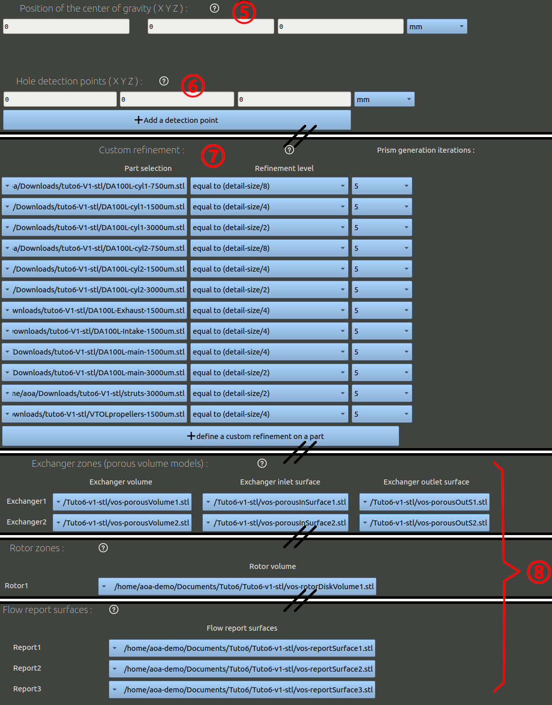
- Skip the moving parts and go down to the center of gravity setting. Set it to 0 / 0 / 0 mm.
- The hole detection point is used to check the integrity of surfaces given. It is a point that is inside the solid given. You can check for holes in multiple solids by setting multiple points. Here we can set a couple: one inside the fuselage and one inside the engine. The coordinates 0 / 0 / 0 (inside the fuselage) and optionally 465 / 0 / 30 mm (inside the engine).
- Refinements of the parts need to be done. Set them as below
- Set the exchanger volume or surfaces, the rotor zone, the flow report surface and go to the bottom to create the geometry.