Next: 5 Create a configuration Up: tuto Previous: 3 Importing airfoils Contents
Modeling the wings
A popup window will appear for you to set parameters for the new part. for the wings:
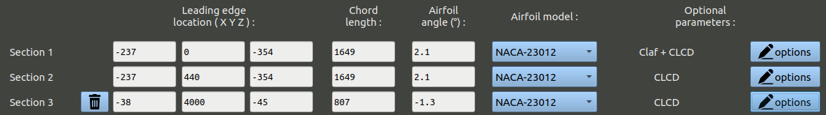
This surface will mainly model the wings, but should also model vertical force effects of the fuselage. We will use two tricks to obtain a more realistic aerodynamic result:
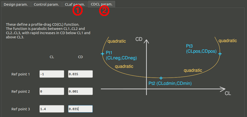
Click 'OK to validate the optional parameters.
NB: The CLaf parameter should only be used on the Y=0 section. The CLCD parameters can be used for all section of this wing surface. This parameters will not be used for the other surfaces.
You may click '3D view of the part' if you want to open an AVL window of the part geometry. Use the spacebar to close this window.
Finally, click 'Ok' to validate the part.
Modeling the horizontal empennage
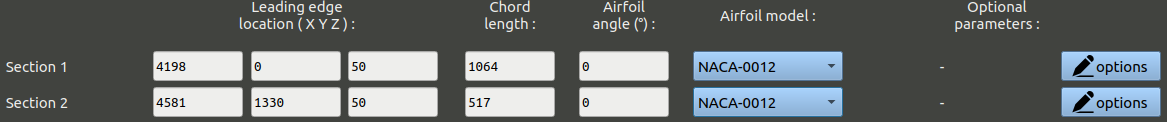
We will now add another surface to model the horizontal tail. Proceed similarly to the wings surface, but without adding any optional parameters. Here is the sections table:
Modeling the vertical empennage
Add another part for the vertical tail, using the following sections table:
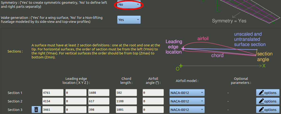
NB: The symmetry parameter must be switched to 'No', as this is a vertical surface placed on the Y-normal plane.
Modeling the fuselage
The lift generated by the fuselage has been modeled with the wing, but not the lateral forces that can be generated in case of sideslip angle. To do that we need to create a vertical surface.
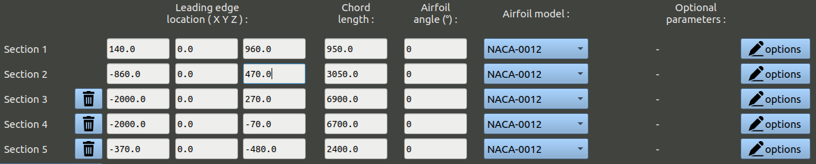
NB: The symmetry parameter must be switched to 'No', as this is a vertical surface placed on the Y-normal plane.
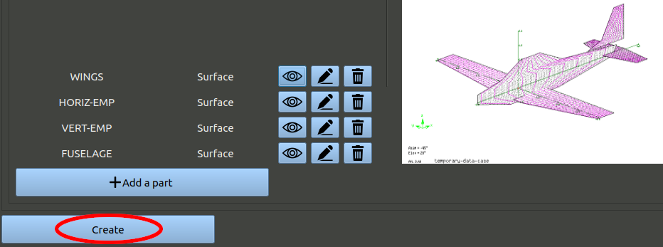
Now that you have the 4 parts, click 'Create' at the bottom to validate the geometry.