Next: 4 Creating the analysis Up: tuto Previous: 2 Creating a new Contents
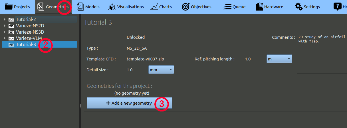
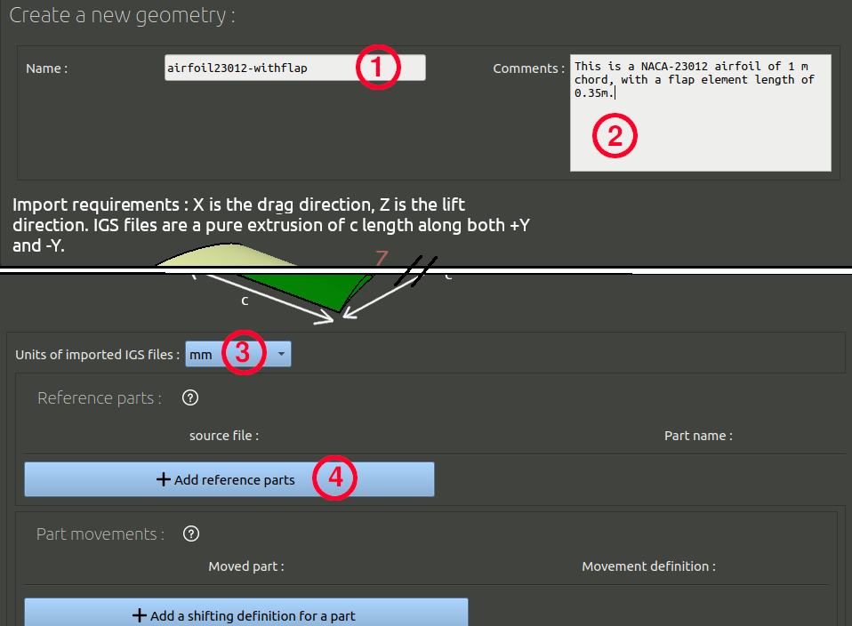
We have defined the primary and the flap at zero-deflection as reference parts. We will now define how the flap must be updated when a command angle will be given.
With this setting, the flap will be rotated with the command angle. We must now add an additional setting for the 0° deflection angle. For that deflection it is better to use the alternative shape of the flap that goes through the primary, in order to be sure no tiny gap is left between the two parts:
With this definition, when you will request a flap deflection of 0° the reference flap will be replaced by the flap-bump.igs file. This is called a 'shift', it can be used to model translation, deformation or any kind of movement.

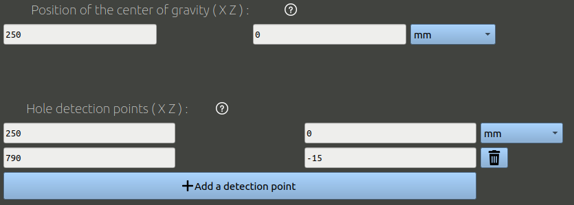
Finally, add Center of gravity and a hole detection points at X=250 mm ; Z=0 mm, which is a point inside the primary. The Center of gravity is needed to measure the pitching moment.
The hole detection point is used to check the integrity of surfaces given. It is a point that is inside the solid given. The CFD mesher will consider the volume found on this point to be the "inside" of the object, where no airflow is present, and will not mesh it, but will mesh the volume he finds outside this one.
It is possible to add multiple hole detection points. In this case you can add a second hole detection point at X=790 mm ; Z=-15mm. This point will check the airproofness of the flap for all its positions from 0° of deflection to 35° of deflection.
Click the 'Create' button to validate, the igs files will be imported and converted, and the page will refresh.
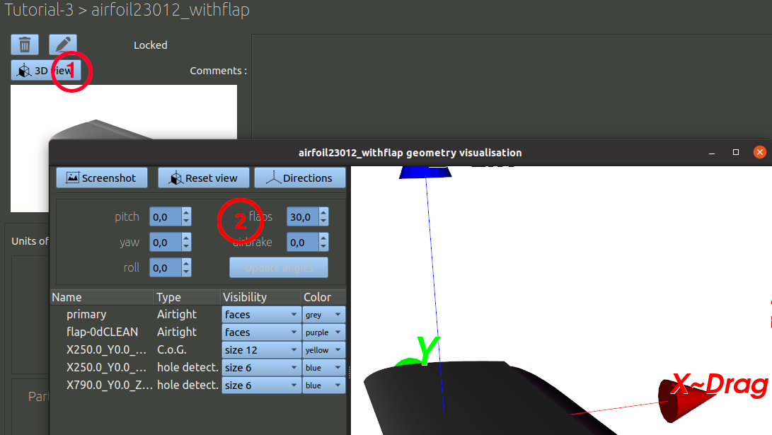
Once the geometry is created, you can check the parts movements is set properly visually:
Then, at the bottom of the geometry page, click the button to create a new configuration. Set the flap command angle of 0° with a corresponding name.
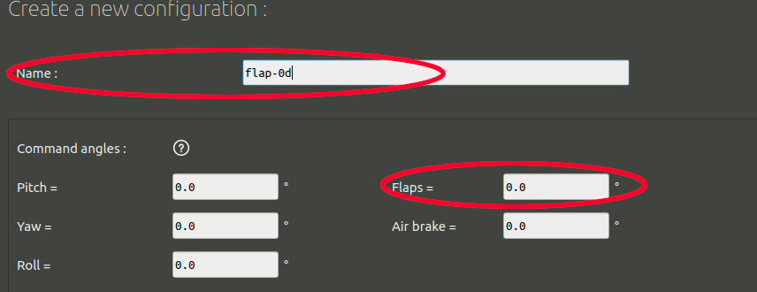
Below the settings for command angles you may find a frame called 'custom measurements' with blue buttons, you may ignore this frame for now as we will not demonstrate these functionalities in another tutorial.
At the bottom of the configuration creation page, there is a frame called 'Solving duration'. It contains parameters that can speed up or slow down processing time. If you don't make any change, everything will be run with a "standard" iteration quantity, which is 2500 iterations for the turbulence model selected in this tutorial.
But often, as the angle of attack is increased, when stall appears, more iterations can be needed to obtain a good convergence. We will later set up computations with angles of attack from -4 to 20°. For this tutorial, we will decide that we are going to use a standard iteration quantity for the low angles of attack (less than 12°), but a 'long' iteration quantity (3000it) for the high angles of attack when stall may happen, just to be sure. We can do that by defining, the following parameters:

Finally you can click the "Create" button to finalize this configuration. Another configuration must be made with flap deflected downward. To do that, go back to the bottom of the geometry page to find the configuration creation button, and proceed the same way as we just did, but with a 30° flap deflection instead of 0°.