Next: 4 Setting up the Up: tuto Previous: 2 Creating a new Contents
Before adding the configuration, we need to define modeling laws for our propeller and heat-exchanger. Let's start by creating a model for our water radiator. Its core will be modeled as a porous volume, while the water boxes and frame are modeled as airtigh surfaces. The law we must define will be applied to the porous volume.
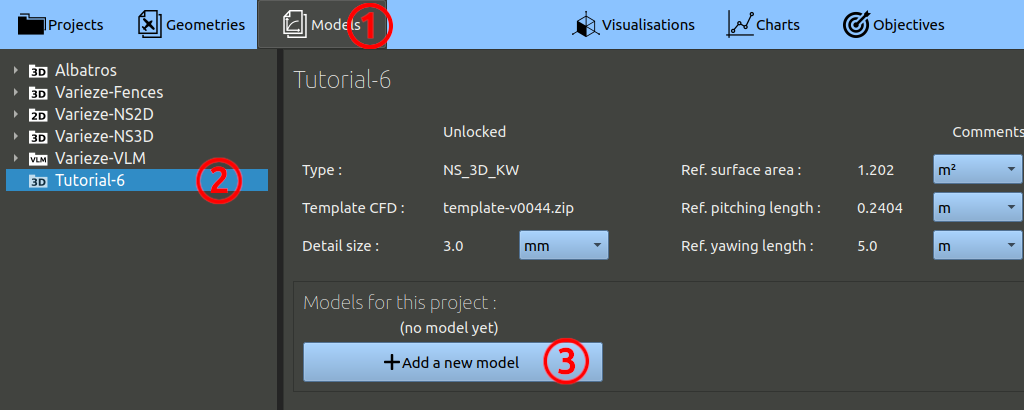
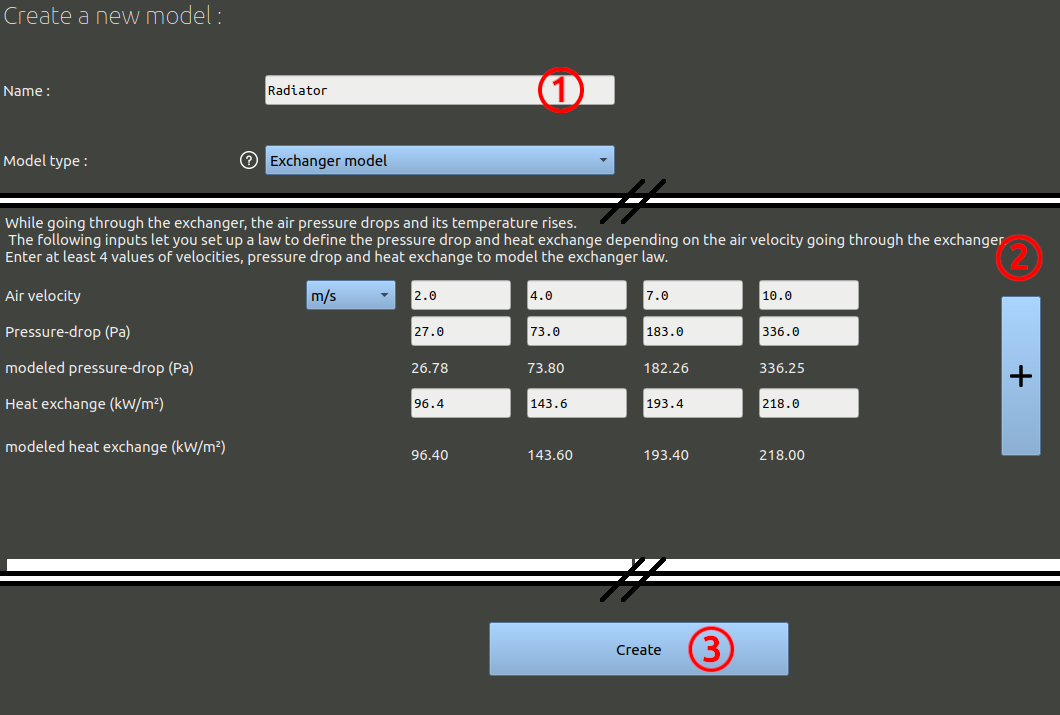
The temperatures are not modeled in the solver. The law will simply allow to make a cooling estimation at the end of the run, according to the air flow rate found passing through the radiator in the computation.
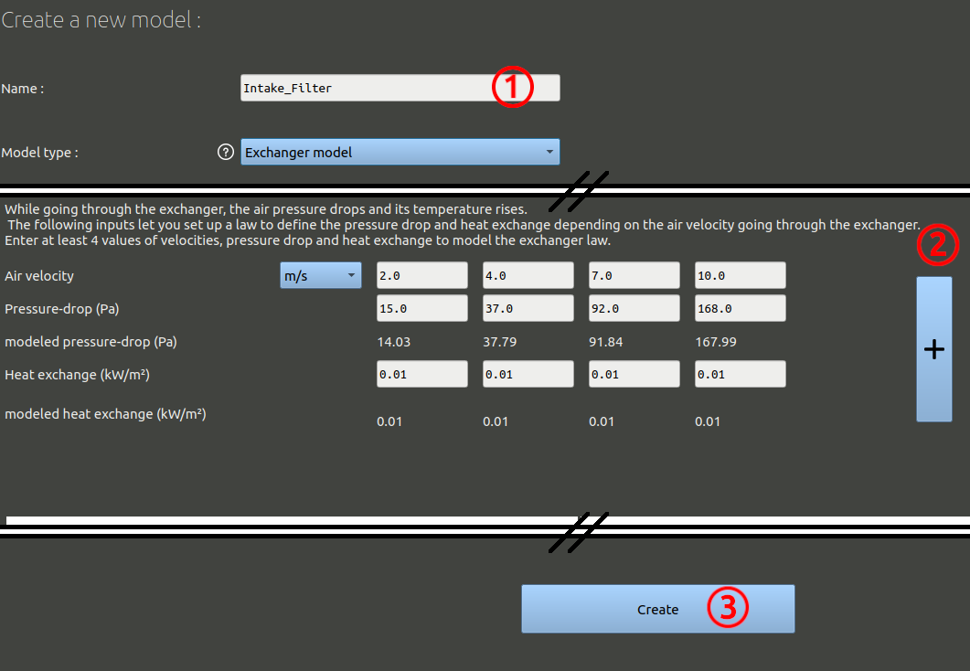
Repeat the operation for the 'Intake-Filter'. Air intakes can be hard to model accuratly when their mass flow is very high. Placing a porous zone in their intake duct generally make results more reliable. The software can also be used to optimise the air filters, find the best shape for them.
For this pourous zone, only the porous law interest us. The air filter doesn't exchange heat, but the model was created for heat exchangers. Put a minimal value for heat exchange and ignore the exchange output from this model when reading the results later on:
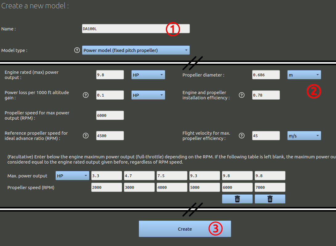
Add the last model :
These models we created must now be associated to our geometry to define a specific flight configuration. Come back in the 'Geometry' tab, select the geometry we created before and add a new configuration :
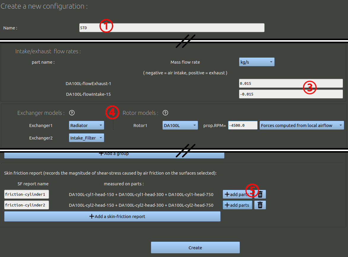
As in Tutorial-4 you can ignore the step "Build the configuration" as we are sure no holes are present in the .stl files. The configuration will be built automatically when needed.