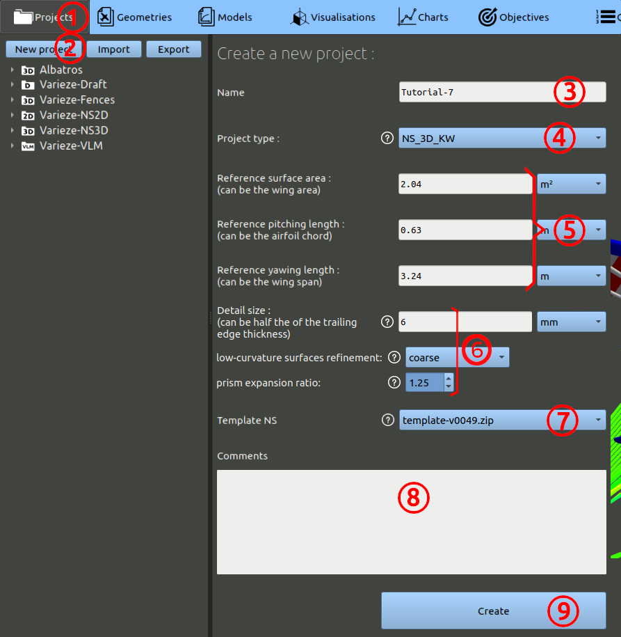
First, we have to create a project:
- In the navigation bar, click 'Projects'
- Then click 'New project'
- Enter the name of your choice for the project. (ex: 'Tutorial-7')
- For the project type, select 'NS_3D_KW', which is Navier-Stokes 3D K-Omega abreviated (a K-omega SST turbulence model will be used).
- Set the parameters : Ref surface area = 2.04 m² ; Ref pitching length = 0.63 m ; Ref yawing length = 3.24 m.
- The detail size parameter should be set at 6 mm. The other meshing parameters can be set to the default values: coarse refinement for the low-curvature surfaces and a prism expansion ratio of 1.25.
- The Template NS is a script version for processing the Navier-Stokes runs. Choose the one with the highest version number.
- You can add comments, but it is optional.
- Finally, click the 'Create' button.
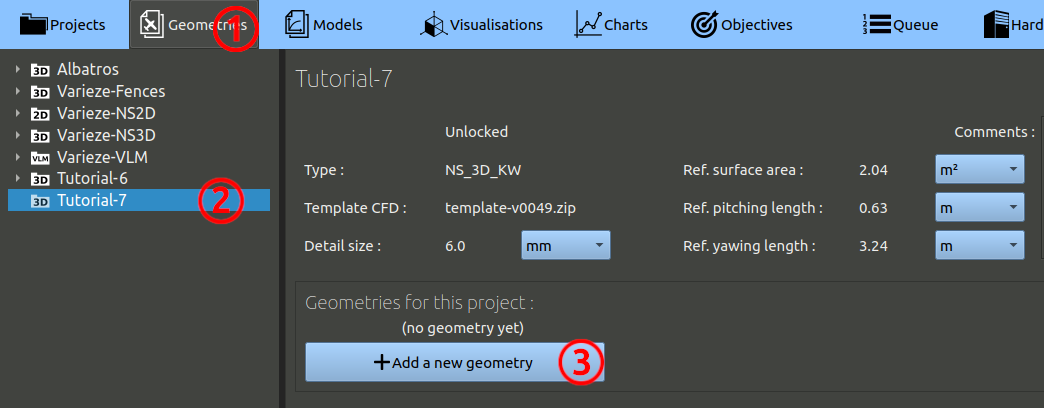
Then, we can create our first geometry:
- In the navigation bar, click 'Geometries'
- In the tree on the left, choose the project you created at the preceding step.
- Finally, click the 'Add a geometry' button.
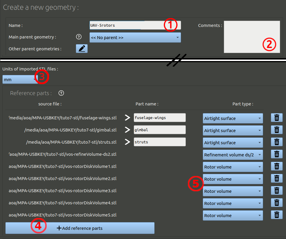
In the geometry creation form, set the parameters as:
- Name it 'UAV-5rotors' for example.
- You can add comments, but it is optional.
- Under the spitfire image highlighting the axis expected in the CAD, set the units of the CAD. The files provided have been exported in millimeters.
- Click the button to add reference parts, select the path to the stl files provided before, add all the stl files.
- Edit the part types. The 5 rotors must be set to "Rotor volume".The part "vos-refineVolume" is made of several volumes build around leading edges and trailing edges, this part must be set to the type "Refinement volume ds/2". Cells within these volumes will be refined with a size being half of the detail size.
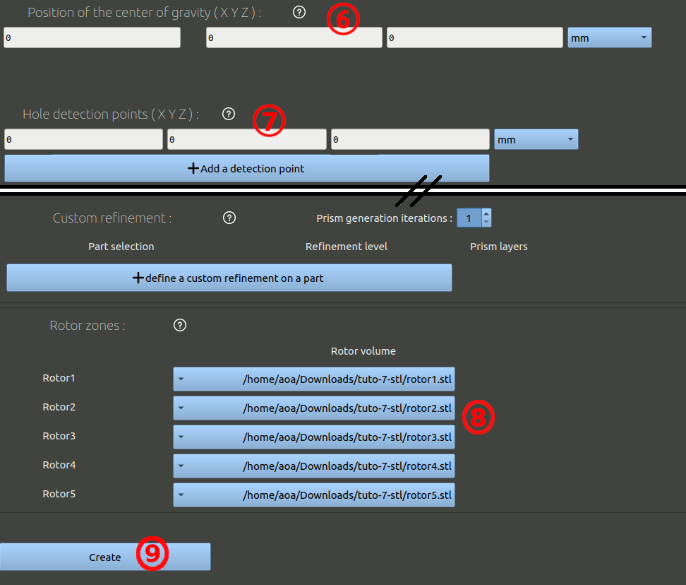
- Skip the moving parts and go down to the center of gravity setting. Set it to 0 / 0 / 0 mm.
- The hole detection point can be set at the same coordinates.
- Set the rotor zones with each rotor part, without changing the order.
- Go to the bottom to create the geometry.
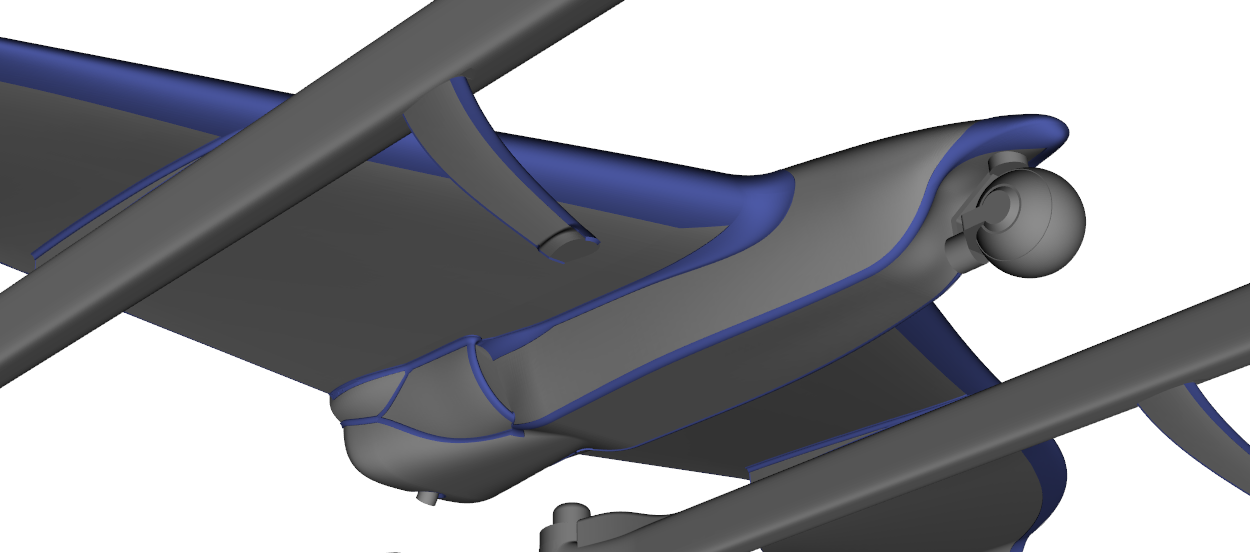
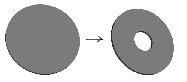
NB: There are a couple of differences in this geometry compared to what was shown in the preceding tutorials. First, the rotors are modeled with a washer shape instead of a closed cylinder. The airflow close to the spinner can be tricky to model. Meshing can be difficult in this area and the resulting velocity can be inaccurate. We demonstrate here a trick that can avoid such problems. By removing the central part of the cylinder, we ignore a small part of the propeller effect, but the meshing and solving can be more reliable in some cases.
Another difference is that instead of having distinct surfaces of the UAV placed in a distinct part to define local refinements, a specific volume is defined as a reference part, a volume to be refined. This volume part, shown in blue in the following image, looks like tubes placed on leading edges, trailing edges and other edge lines of the UAV. The part is actually composed of multiple volumes, and all cells within these volumes will be refined to 3mm because of the parameters we chose (volume refinement to detail-size/2, the detail size of the project being 6mm). This volume is made to barely offset the surface, in order to not create too many cells.